In recent years, many generator sets have experienced a crack and leakage accident in the main steam monitoring thermometer casing, which has seriously affected the safe and economic operation of the unit. Therefore, many power plant thermal control specialists cooperated with the metal professional to strengthen the maintenance and inspection of the thermowell, and adopted some targeted measures for the selection and installation of the thermowell, and received good results.
I. Case of Thermowell Casing Cracking The thermal power unit usually uses thermocouples to monitor the temperature of high-temperature and high-pressure steam with very high flow rates. Take the subcritical unit as an example, the pressure is 18MPa, the temperature is 540°C, and the flow rate can reach 40-60m/s. Such a high flow rate and high temperature and high pressure will have a very large and harmful impact on the thermometer casing. In recent years, a large number of thermometer casing fractures and leakage accidents have fully demonstrated that it is necessary to attach importance to and strengthen the supervision and inspection of the thermowell casing.
Since 2000, there have been several typical cases of thermowell casing rupture in East China:
(1) On September 27, 2000, a thermocouple temperature thermowell at the outlet of the desuperheater of a No. 2 boiler of a self-contained power plant was cracked, and a large amount of steam was ejected outward. The dismantling inspection after shutting down the furnace revealed that the crack occurred at the junction of the cone and the infeed, and the crack accounted for 70% of the entire circumference.
(2) On June 5, 2005, the thermowell of the adjustment unit of the No. 1 unit (125MW) turbine of a power plant leaked and was urgently repaired.
(3) On August 27, 2005, a No. 1 unit (300MW) of a power plant was urgently repaired due to a leakage of the temperature sensor casing weld point at the main steam temperature.
(4) On July 25, 2006, during the normal operation of the No. 2 generating unit (600MW) of a power plant, it was found that the temperature of the inlet pipe of the left high-pressure main steam inlet pipe was suddenly cracked at the welding point of the measuring point thermometer and the steam burst out. , Immediately stop and stop emergency repairs. Post analysis revealed that there was a large area of ​​unwelded area in the weld.
(5) On March 12, 2008, the overheating of the high pressure cylinder of Unit 2 unit (600MW) was found to be broken. The lower half of the steam turbine thermometry element thermometer casing was found to be broken, and the falling part was stuck in the first stage static blade. Steam side.
Second, the analysis of the causes of the fracture of a typical thermometer casing Through the analysis of the causes of the fracture of the thermometer casing, there are roughly:
(1) The thermometer casing is impacted by high-speed fluid, the load is too large, and the stress exceeds the limit;
(2) The processing defect of the thermowell itself leads to stress concentration and is prone to fracture;
(3) Excessive vibration of the pipeline causes fatigue damage to the thermometer casing;
(4) When the fluid flows through the thermowell, the vibration of the thermowell is induced, that is, the natural frequency of the thermowell and the frequency of the vortex shedding generate resonance. This resonance phenomenon can cause the thermometer casing to be damaged faster, resulting in fracture.
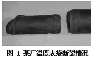
In practical applications, it is common to find thermowells of the same batch, same size, and same insertion depth. One root may not be damaged for 6 to 10 years or more, and the other may be in a very short time. A fracture accident occurred. If two 600MW units of a power plant were put into operation in 2000, the 2 thermowells of Unit 2 had occurred two fracture accidents. Compared with Unit 1 which was put into operation one year earlier, it was safe and sound. Through analysis and comparison, it was considered that the thermometers of Unit 2 were caused The main reason for the frequent fracture of the casing is the resonance fatigue caused by the thermometer casing fatigue. The fracture picture of the thermowell of Unit 2 is shown in Figure 1.
2.1 Stress Analysis of Thermowells Figure 2 shows the installation of thermowells. The radius of the thermowell is R, the insertion depth is L, and the pressure of the fluid in the pipeline is P. For convenience of analysis, assuming that the circulation is full, the cross-section force of the thermowell is shown in FIG. 3 .
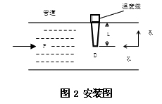
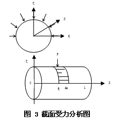
Immediately after the system was put into operation, the insert part of the thermometer sleeve was subjected to a positive force in one direction, as shown in the upper diagram of Fig. 2, thus forming a torque force system around the junction of the thermometer sleeve and the pipe. Let its minimum force unit be dx and the minimum force moment unit be dm, and the moment M that the insert part can bear is:
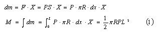
The force analysis after the fluid velocity is stable is shown in Fig. 4. At this time, the front and back sides of the thermometer sleeve are under pressure, but due to resistance of the thermometer sleeve, a certain pressure loss is caused, making the front pressure greater than the back pressure. The pressure, set this pressure difference as ΔP, then the formula (1) to calculate the thermowell casing torque is:
2.2 Thermowell casing resonance mechanism analysis The fluid induced vibration mechanism can be roughly divided into vortex shedding, turbulent flutter, and fluid elastic perturbation. The vibration caused by vortex shedding is the earliest and most complete mechanism studied.
In subsonic lateral flow, any non-streamlined tail will generate vortex shedding if there are enough trailing edges. When the vortex alternately disengages from both sides of the object, periodic lift and resistance are generated on the object. This change in the streamline spectrum will cause changes in the pressure distribution, which will result in changes in the magnitude and direction of the fluid pressure acting on the object, eventually causing the object to vibrate.
The force of thermowell vibrations, which is usually caused by vortex shedding, is negligible. However, when the frequency of vortex shedding is closer to the natural frequency of the thermowell, the following phenomena will occur:
(1) The phenomenon of “beating†occurs when the vorticity intensity is cyclical, high and low; the correlation between the wake length and wake length increases, and the resistance increases; and the lateral lift increases by 2-3 times;
(2) Frequency locking When the vortex dominant frequency is very close to the temperature of the bag vibration frequency, the vortex frequency no longer rises with the increase of the flow velocity, but maintains the same frequency as the structure, which is called frequency lock. The dominant frequency does not change until the flow rate is large and the frequencies of the two are far apart;
(3) Detuning Due to the nonlinear coupling, the maximum steady-state vibration amplitude does not occur at the vortex frequency equal to the structural natural frequency but in the middle of the frequency locked section.
Therefore, in order to avoid the resonance phenomenon, the design of the thermowell should meet the following relationship:
Among them: fs - vortex shedding frequency (excitation frequency of fluid impact);
f1—The natural frequency of the thermowell.
In general, the excitation frequency generated by the fluid impact is much lower than the natural frequency of the thermowell. Therefore, in the absence of other excitation conditions, the thermowell design should meet the requirements of formula (3). According to the American Society of Mechanical Engineers Standards (ASME), the ratio of vortex shedding frequency to the natural frequency of the thermowell should be less than 0.8.
If the requirements of formula (3) cannot be met, additional measures must be taken to avoid resonance.
Third, to prevent the thermometer casing fracture measures For the above theoretical analysis and practical experience, in order to improve and improve the safety and reliability of the thermometer casing, to extend its service life, should do the following preventive measures:
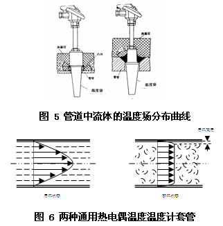
(1) Strictly control the depth of insertion of the thermowell. From formula (1) and formula (2), it can be seen that when the insertion depth increases, the force applied to the protective sleeve increases by a factor of two. Since the main steam temperature and flow velocity of a large unit has reached a turbulent state, the thickness of the laminar bottom layer immediately adjacent to the wall is usually very thin. Therefore, when measuring the temperature of a fluid in a turbulent flow channel, simply inserting the thermowell into the isothermal zone of the fluid can accurately measure the temperature of the fluid without inserting it into the center point of the pipe. This shortens the length of the thermometer bag cantilever, effectively reducing the amplitude of its end point. Figure 5 shows the temperature field distribution of the fluid in the pipeline under laminar and turbulent flow conditions.
(2) Optimize and select the diameter of the thermowell when ensuring the necessary thermowell strength. From equation (1) and equation (2), it can be seen that when the diameter of the thermometer casing increases, the force of the watch bag increases linearly. Therefore, when selecting the diameter of the watch bag, it is necessary to reasonably ensure the strength of the casing. Also try to stagger the resonance danger zone as much as possible.
(3) Change the cross-sectional shape and machine the surface to the structure shown in Fig. 6 so that the fluid does not generate vortex shedding.
(4) Strictly control the quality of inspections, do a good job in the inspection of the thermowell casing materials, combine the overhaul of the unit and do a good job in the inspection of weld joints, and strictly prevent the occurrence of abnormal accidents such as cracks and fractures at the weld joints.
(5) When the system is put into operation, sudden full opening of the valve on the pipeline is avoided. From the formula (1), it can be seen that the thermowell will be subjected to a large unidirectional force immediately after the valve is opened. Therefore, when the system is just put into operation, the valve must be opened slowly to gradually increase the pressure of the system. , Minimize the pressure difference between the front and back of the thermometer casing to avoid the casing from breaking due to excessive force in one direction.
We provide high precison CNC Machining part custom-made service
Main process: Precision CNC machining part
Material:Aluminium6061/6063/7075/5052 etc, Stainless steel303/304/400/316, SteelQ235,20#,45#etc,
Brass:C36000(C26800), C37700(HPb59), C38500(HPb58),C2200(CuZn37),C28000(CuZn40) etc,Copper;Beryllium bronze copper.
Process:CNC turning,CNC milling, CNC grinding;CNC Lathe machining, CNC boring;CNC drilling, surface treatment
Surface treatment:Hardness anodizing black/clear, steel oxidizing dark-blue, electro-polishing, electroless nickel plating, silver plating, golden plating etc
Tolerance:+/-0.001mm or +/- 0.00004"

CNC Machining
CNC Machining,CNC Milling Machine,Milling Machine,CNC Mill
Baoding Henglian Mechanical Co.,Ltd , http://www.hengliancasting.com