What should you watch out for when using a sensor? How to detect sensor failure?
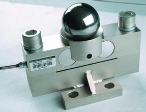
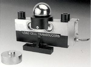
Weighbridge sensors: Weighbridge sensors are actually devices that convert a mass signal into a measurable electrical signal output. The sensor must first consider the actual working environment in which the sensor, this sensor is essential for the correct selection, Gordon continued weighbridge manufacturers of sensors related to the platform if it works as well as its safety and service life, and the whole weighing the reliability Sex and safety. The role of the load cell in the use of electronic loadometers is ubiquitous, because the resistance strain load cell itself is a robust, durable, reliable electromechanical product, but in order to ensure the accuracy of the test Problems in this area:
1. The sensor should be made of a hinged copper wire (cross-sectional area of ​​about 50mm2) to form an electrical bypass to protect them from damage caused by welding current or lightning strikes. In the use of sensors, strong heat radiation must be avoided, especially one-sided strong heat radiation.
2. The electrical connections (such as the signal cable of the sensor should not be arranged in parallel with the power line or control line (for example, do not put the sensor signal line and the strong power line and control line in the same pipe) if they must be in parallel Place, then, the distance between them should be kept above 50CM, and put the signal line with a metal tube.
3. Some “baffles†should be set around the load cell and even covered with a thin metal plate. This prevents impurities from contaminating the sensor and some moving parts. This “staining†tends to make the moving part uncomfortable and affect the weighing accuracy. Whether the system has sports or not, it can be judged by the following methods. That is, add or subtract approximately one-thousandth of the rated load on the weighing platform to see if the electronic loadometer indicates whether it has been reflected or not, and it indicates that the movable part has not been “contaminatedâ€.
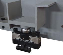
4. Use structural accessories with automatic positioning (reset) as much as possible, such as ball bearings, joint bearings, positioning fasteners, etc. They can prevent some lateral forces from acting on the sensor. It should be noted that some lateral forces are not caused by mechanical installations, such as lateral forces due to thermal expansion, lateral forces due to wind, and lateral forces caused by the vibration of agitators on certain vessel-type instruments. . Some scales must have accessories attached to the scale body (such as conveyor scales for container scales, etc.). We should allow them to be as soft as possible in the direction of the sensor loading the main shaft to prevent them from “eating†the true load of the sensor. Together, it causes errors.
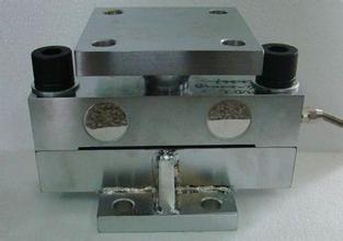
5. To take light and light, especially small-capacity sensor made of aluminum alloy elastomer, any impact, drop, its measurement performance may cause great damage. For large-capacity load cells, in general, it has a large self-weight, so it is required to use appropriate lifting equipment (such as chain hoists, electric hoists, etc.) as much as possible during handling and installation. The base mounting surface on which the sensor is mounted should be flat and clean, without any oil film, adhesive film, etc. The mounting base itself should have sufficient strength and rigidity, generally higher than the strength and rigidity of the sensor itself.
6. Although the load cell has a certain overload capacity, during the installation of the weighing system, the overload of the sensor should still be prevented. It should be noted that even a short period of overloading may cause permanent damage to the sensor. In the installation process, if it is really necessary, replace the sensor with a height pad such as a sensor, and finally replace the sensor. In normal operation, sensors should generally be provided with mechanical components for overload protection. If the sensor is fixed with a screw, a certain tightening torque is required, and the screw should have a certain screw thread depth. In general, the fixed screw uses a high-strength screw.
7. In any case, the power line and control line should be twisted together to a degree of 50 revolutions per meter. If the sensor signal line needs to be extended, a special sealed cable junction box should be used. If this type of junction box is not used and the cable is directly connected to the cable (tin soldering tip), special attention shall be paid to the moisture proof of the seal. After the connection, the insulation resistance shall be checked, and it shall meet the standard (2000-5000M), if necessary, The sensor should be recalibrated. If the signal cable is long and high measurement accuracy is to be ensured, cable compensation circuits with relay amplifiers should be considered.
8. Level adjustment: Level adjustment has two aspects. First, the mounting plane of a single sensor mounting base should be leveled with a spirit level. On the other hand, the mounting surface of multiple sensor mounting bases should be adjusted to a horizontal plane (quasi-geometry) as far as possible, especially if the number of sensors is more than three. We should pay more attention to this point in the weighing system. The main purpose of doing so is to make the load on each sensor basically consistent. The loading direction of each electronic loadometer load cell is determined, and we must load the load in this direction when we use it. Lateral forces, additional bending moments, and torque forces should be avoided as much as possible.
9. All cables leading to or from the display circuit should be shielded. The connection and grounding point of the shielded wire should be reasonable. If it is not grounded through the mechanical frame, it is grounded at the outside, but the shielded wire is not grounded after it is connected to each other and it is floating. Note: There are 3 sensors that are fully connected and the sensor itself is 4-wire, but it is replaced with a 6-wire system in the terminal box. The sensor output signal readout circuit should not be placed in the same box with devices that can generate strong interference such as “silicon control, contactors, etc.†and devices with significant heat generation. If this cannot be guaranteed, they should be considered in their Set up the baffle isolation, and place the fan in the cabinet.Electronic circuits used to measure the output signal of the sensor should be equipped with independent power transformers as much as possible, and do not share the same main power supply with devices such as contactors.
The steps to find sensor faults are as follows:
1. Check the resistance between positive excitation (+EX) and negative excitation (-EX) in the junction box with a multimeter (in the junction box, the upper side of the signal cable connection to the instrument). Its resistance of approximately 400 / number of sensors. Use a multimeter to measure the resistance between the positive output (+Si) and the negative output (-Si) of the total output. The resistance is approximately 2500/section (Note). If you find that the resistance is incorrect, press Next to continue.
Note: The section is the vertical direction of the weighing platform, the face of each pair of sensors. That is, a section generally has a pair of sensors. For example, a 30T truck scale has 4 sensors divided into two sections with a section number of 2.
2. Disconnect the sensor one by one. Measure the impedance between the positive and negative excitation terminals or the positive and negative output terminals using the above method to detect the damaged sensor. If there is no problem with this step check, press step to continue searching.
3. Place the weights on each section of the weighing platform in order. If the value of the section is found to be incorrect, place the weight on the sensor corner of this section (pressure angle), find the bad sensor, and replace the sensor. .
4, or off a +Si, -Si end of a sensor in the absence of electricity under the test resistance value should be around 350.
Dear customers and friends! Xiangxi continued production of the sensor on the loadometer quality and cheap! Absolute sincere service Absolutely sincere price Absolute product quality Xiang continued Tip: Due to the sensor model, specifications are not the same, want to understand what you need the sensor specifications and price, please contact us! !
KINMAN, a leading manufacturer in China, specializing in a galaxy of Trailers and Trailer Parts .
Trailers: ATV Trailer , utility trailer, Box Trailer , Watercraft Trailer, Snowmobile Trailer, Car Trailer , etc.
trailer parts & trailer accessories: Hitch Ball , Ball Mounts, Trailer Coupler , Trailer Jack , Winch, Wheel Hub , Trailer Light , Pan Fitting , Tie Down , etc.
For detailed information, pls feel free to contact us.
Trailer
ATV Trailer, Timber Trailer, Box Trailer, Boat Trailer, Utility Trailer, Livestock trailer
NINGBO KINMAN AUTO PARTS CO.,LTD. , https://www.kinmantrailer.com