1. The main circuit connection
1) Symbol G is the grounding terminal of the inverter box. To ensure the safety of the inverter , this point should be grounded according to the national electrical code. The grounding resistance should not exceed 4Ω.
2) Inverter power input terminals with R, S, T said. It is recommended to use the FAB with air circuit breaker with leakage protection to connect to the three-phase power supply, without regard to the phase sequence when connecting. It is not allowed to start or stop the inverter with the FAB switch. It should be controlled by the panel operation keys FWD and REV.
3) Inverter power output terminals with U, V, W said. According to the requirements to determine the forward or reverse, if the steering is wrong, any two-phase exchange can be. Output capacitors and surge absorbers are strictly prohibited. Connection with the motor should not be too long, the power of not more than 3.7kW of the motor, the length should be less than 50m, otherwise additional line filter (0FL) (generally sold separately).
4) The terminals RO and TO are auxiliary inputs for control power supply. They have two functions, one is for external anti-radio interference filter and the other is for feedback braking (see product manual).
5) DC reactor connected to the terminals P1 and P (+), the purpose is to improve the power factor. When the factory is connected, the two terminals are short-circuited. When DC reactor is used, it should be removed first and then DC reactor (optional).
6) The external braking resistor is connected between terminal P (+) and DB. When the power is less than 7.5kW, the inverter has a built-in braking resistor. When frequently starting or stopping, the built-in capacity is not enough, you need to use external resistor (optional). When the motor power is not less than 15kW, in addition to the external braking resistor, increase the braking capacity Moving unit (optional), connected to P (+) and N (-)
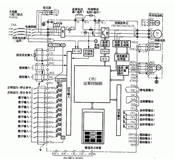
2. Control terminal connection
1) For external potentiometer, the power supply DC + 10V can be taken from terminal 13 and common terminal 11, and set the frequency with 1 ~ 5kΩ potentiometer.
2) When the voltage signal is set to be input, it can be input from terminal 12 and common terminal 11 for frequency setting. The input impedance is 22kΩ and the input voltage is DC0 ~ ± 10V. PID feedback signal can also be input.
3) When setting current signal input, input from terminal Ai1 or Ai2 and common terminal M. Frequency settings, the input impedance of 250Ω, input DC current of 4 ~ 20mA, you can also enter the feedback signal PID control.
4) ON / OFF of FWD input terminal FWD is forward rotation, REV is reverse ON / OFF, X1 ~ X9 can be selected as command signals such as motor alarm, alarm reset and multi-step frequency selection. Terminal CM is common point.
5) PLC signal power supply, input terminals PLC and M, PLC output signal power DC24V.
6) Transistor output terminals Y1 ~ Y4, common terminal CME can output monitoring signals, such as running, frequency arrival, overload forecast signal. The maximum current when the transistor is on is 50mA.
7) The total alarm output relay output by the 30A, 308,30C, contact capacity AC250V, 0.3A, can be used to control the alarm output, the signal protection action.
8) Optional signal output relay, you can choose a similar signal with the Yl ~ Y4 terminal as the output signal.
9) Communication interface. Terminals TX (+) and TX (-) are used as input / output terminals for RS485 communication. Up to 31 inverters can be controlled. The terminal SD is used for the communication wire shielding layer, this terminal electrically floats (not necessarily the zero potential, but the common ground in the circuit).
10) In order to prevent the input signal interference, the general analog signal to be shielded wire, and the length as small as possible 20m or with ferrite ring (with the same around 2 to 3 turns), and then parallel 0.022μF, 50V capacitor, Filter and other ways.
Frame steel electric scooters are generally more compact and stylish appearance, generally less than one meter easy to carry. Electric scooters can be folded, fold up small footprint can easily carry. For office workers, you can go out to ride the Electric Scooter to the bus station by car, and then when the bus can be folded to carry, work when the trunk can be put elevator. Electric scooters do not need people to rely on the strength of the waist twisting and foot push to promote skateboarding, but the use of electricity as energy, battery capacity. Electric scooter battery in addition to large capacity, there are high-power motor, scooter can ensure long life, with strong power and climbing ability. High strength steel frame, light weight, large span. Production factory, processing performance is good
Frame Steel Electric Scooter,Electric Scooters For Adults,Aluminum Alloy Electric Scooter,Custom Steel Frame Electric Scooter
QuZhou Benneng Vehicle Co.,LTD , http://www.cn-ebikes.com